Parallel Printer Cables: IEEE 1284, DB25 and Centronics
IEEE 1284 parallel printer cables explained: DB25 and Centronics 36 connectors, cable length limits, modes, and when a USB-to-parallel adapter works.
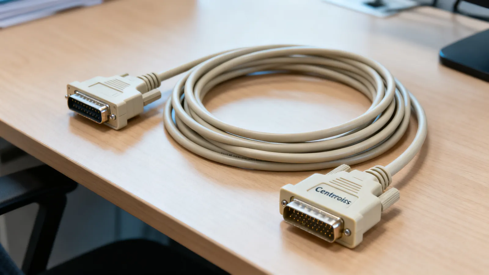
A parallel printer cable joins a computer’s DB25 parallel port to a printer’s 36-pin Centronics port, and the standard that governs it is IEEE 1284. If the printer still works and the computer still has the port, a compliant IEEE 1284 cable up to 10 m (32 ft) is the correct part. If the computer has no parallel port, a USB-to-parallel adapter works for printers but not for other parallel-port devices such as programmers or dongles.
The three connectors you will meet
The parallel port on a PC is a 25-pin D-subminiature connector, usually called DB25. The printer end is a 36-pin Centronics connector. IEEE 1284 names them by letter:
| IEEE 1284 name | Connector | Where it goes |
|---|---|---|
| 1284-A | DB25 | Computer parallel port |
| 1284-B | 36-pin Centronics | Printer |
| 1284-C | Mini-Centronics 36 | Smaller printers and some peripherals |
A DB25 to Centronics cable is the classic parallel printer cable. The DB25 end is male on the cable, matching the female port on the computer. The Centronics end is a 36-pin ribbon-style connector with a wire bail latch. Mini-Centronics 36 is a different shell and does not mate with the standard Centronics 36.
Do not confuse the DB25 parallel port with the DB25 serial port. They use the same shell but different signals. A DB25 serial port follows RS-232 pin assignments, which are covered in RS-232 serial pinouts: DB9 and DB25. Plugging a parallel printer into a serial port, or the reverse, will not work and can stress the interface.
What IEEE 1284 actually specifies
IEEE 1284 (1994) defines the electrical signalling, the cable, and five operating modes. In plain words:
- Compatibility mode is the original Centronics-style unidirectional transfer, computer to printer. It is the slowest and the fallback.
- Nibble mode sends status back from the printer four bits at a time, using the status lines. It is reverse-channel only.
- Byte mode sends status back eight bits at a time. It needs a port that supports it.
- EPP (Enhanced Parallel Port) is a bidirectional mode intended for devices other than printers, such as drives and adapters.
- ECP (Extended Capabilities Port) is a bidirectional mode with hardware compression and DMA, aimed at printers and scanners.
The mode is negotiated between the port and the device. A cable that meets IEEE 1284 supports all of them. A cheap cable with the wrong wire count may only manage compatibility mode.
What is inside a compliant cable
IEEE 1284-compliant cables use twisted pairs for the data and status lines, with a separate shield or drain wire. The twist and the shield are what allow the longer runs and the faster modes. A cable with flat, untwisted ribbon conductors may work at short length in compatibility mode, but it will not support ECP or EPP reliably.
How long can a parallel printer cable be
IEEE 1284-compliant cables work up to 10 m (32 ft). That is the figure to design to. Shorter is always safer, and most desktop installations use far less.
Length interacts with mode. Compatibility mode tolerates the full length better than ECP or EPP, because the faster modes have tighter timing. If a link is marginal at 10 m, dropping to a shorter cable or a lower mode is the practical fix.
When a USB-to-parallel adapter works, and when it does not
A USB-to-parallel adapter contains a converter chip that presents the printer to the operating system as a USB printer. For printers, this generally works: the adapter handles the printer protocol and the driver sees a printer.
It does not work for other parallel-port devices. Programmers, dongles, EPROM burners, some scanners and industrial controllers expect direct access to the parallel port registers. A USB adapter does not provide that, so the software cannot talk to the device. The same limitation applies to USB-to-serial adapters, which are covered in USB to serial adapters: drivers, levels and pitfalls.
Two more points on adapters:
- The adapter needs the right driver. A chip that the operating system does not recognise will not install, and a counterfeit chip can be blocked by the genuine maker’s driver.
- Adapters with TTL output are not parallel-port adapters. They are for microcontroller work and will not drive a printer.
If the goal is to keep an old printer running, a USB-to-parallel adapter is the usual answer. If the goal is to keep an old programmer or dongle running, the adapter is not the answer; the machine needs a real parallel port, which usually means an older computer or an expansion card.
What goes wrong
The common failures are predictable:
- Wrong cable class. A flat ribbon cable sold as a printer cable may pass a short compatibility-mode job and fail on ECP. Use a cable marked IEEE 1284-compliant.
- Wrong connector gender or shell. DB25 and Centronics 36 look similar to other D-sub and ribbon connectors. Check the pin count and the shell before forcing anything.
- Parallel port confused with serial port. Both can be DB25. The signals are not compatible.
- Length beyond 10 m (32 ft). The link becomes unreliable, and the failure often looks like a driver problem rather than a cable problem.
- USB adapter used with a non-printer device. The device is not seen at all, or the software reports that the port is unavailable.
- Damaged Centronics latch. The wire bail is what holds the connector in place. A bent bail lets the plug walk out and produces intermittent faults.
- Missing or disabled port in the operating system. A port that is present in hardware may need to be enabled in firmware before the driver sees it.
Choosing the right cable
For a printer on a machine with a real parallel port, choose a DB25 to Centronics 36 cable marked IEEE 1284-compliant, and keep the run at or under 10 m (32 ft). For a printer on a machine with only USB, choose a USB-to-parallel adapter and accept that it is a printer-only solution. For any other parallel-port device, plan on a real port.
Label both ends of the cable and note the mode the port is set to. If a job fails, the first checks are the cable class, the length, and whether the port is set to the mode the device expects.
Common questions
How long can a parallel printer cable be?
IEEE 1284-compliant cables work up to 10 m (32 ft). Shorter is safer, especially for ECP and EPP modes, which have tighter timing than compatibility mode.
What is the difference between DB25 and Centronics 36?
DB25 is the 25-pin connector on the computer's parallel port. Centronics 36 is the 36-pin connector on the printer. A parallel printer cable has one of each.
Will a USB-to-parallel adapter work with my old printer?
Usually yes. The adapter presents the printer to the operating system as a USB printer. It will not work with non-printer devices such as programmers or dongles, which need direct access to the parallel port.
Can I use a serial cable as a parallel printer cable?
No. A DB25 serial cable follows RS-232 pin assignments and carries different signals. A parallel printer needs an IEEE 1284 cable with the correct pinout.
Why does my parallel printer only work in one mode?
The port and the cable negotiate a mode. A cable that is not IEEE 1284-compliant may only manage compatibility mode. A compliant cable supports compatibility, nibble, byte, EPP and ECP.
Read next
RS-232 Pinouts: DB9 and DB25 Explained
Complete RS-232 pinout reference for DB9 and DB25 connectors: DTE and DCE pin assignments, voltage levels, cable limits, and the TTL mistake that damages boards.
Null Modem Cables: Wiring, Adapters and Pinouts
A null modem cable crosses TX and RX to join two computers directly. Covers DB9 and DB25 pinouts, adapters versus cables, gender changers and loopback testing.
SCSI Cables, Connectors and Terminators
SCSI cable types explained: 50-pin, HD68 and SCA-80 connectors, narrow vs wide buses, SE, LVD and HVD signalling, termination rules and length limits.