Null Modem Cables: Wiring, Adapters and Pinouts
A null modem cable crosses TX and RX to join two computers directly. Covers DB9 and DB25 pinouts, adapters versus cables, gender changers and loopback testing.
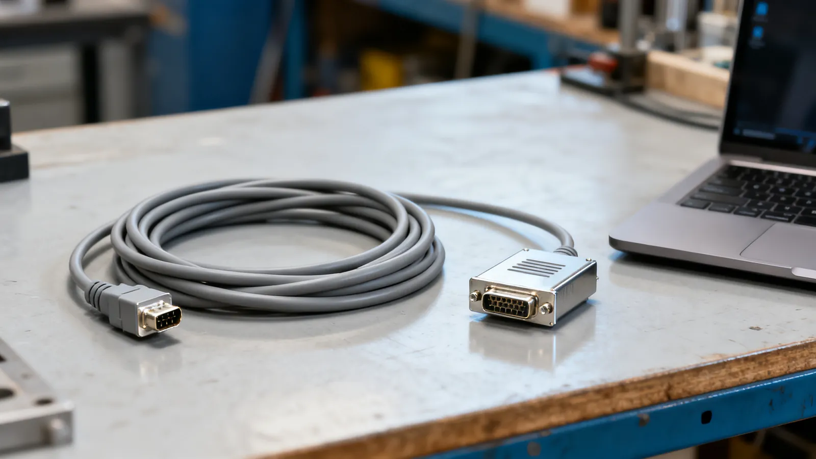
A null modem cable joins two devices that both expect to be the computer end of a serial link. It crosses the transmit and receive lines so that each side’s output arrives at the other side’s input, and it is the serial equivalent of the crossover cable used on Ethernet. You need one whenever two DTEs - two PCs, two terminals, a PC and a router console - must talk to each other with no modem in between.
Why a straight cable will not work
RS-232 defines two roles. A DTE is the computer or terminal; a DCE is the modem or other communications equipment. A straight-through cable is wired pin to pin and is meant to join a DTE to a DCE, because the modem already performs the crossing internally. Put two DTEs on a straight cable and both transmit on the same wire and both listen on the other: nothing arrives. The null modem does the crossing in the cable instead.
Null modem wiring
The minimum link needs only transmit, receive and signal ground crossed or shared. Hardware flow control adds the handshake lines. The full DB9 null modem arrangement is:
| Signal | DB9 pin (side A) | DB9 pin (side B) |
|---|---|---|
| DCD | 1 | 7 and 8 |
| RXD | 2 | 3 |
| TXD | 3 | 2 |
| DTR | 4 | 6 and 1 |
| Signal ground | 5 | 5 |
| DSR | 6 | 4 |
| RTS | 7 | 8 |
| CTS | 8 | 7 |
| RI | 9 | not connected |
Read it as a crossover: TXD on one side lands on RXD on the other, RTS lands on CTS, and DTR crosses to DSR and DCD. Signal ground runs straight through. Some cables tie DTR to DSR and DCD at the same end rather than crossing them; that satisfies software that only checks whether the line is asserted, but it does not carry a real handshake.
A three-wire null modem uses pins 2, 3 and 5 only. It works with software set to no flow control, and fails with software that waits for CTS. If a link comes up and then stalls after a burst of data, missing handshake wiring is the usual cause.
DB9, DB25 and the adapters
The DE-9 connector, almost always called DB9, is the common PC serial port. The DB25 was the original PC and modem connector. The pin functions differ between the two, so a null modem built for one is not the same cable as one built for the other. The full pin assignments for both are set out in the RS-232 serial pinout reference.
Adapters exist in two forms. A null modem adapter is a small shell with a male connector on one face and a female on the other, wired internally as a crossover; it turns any straight extension cable into a null modem link. A null modem cable has the crossover built in and is the better choice for a permanent installation, because every extra mated pair is another point of failure. Adapters are useful when the connector gender on the equipment is fixed and you cannot change the cable.
Gender changers
A gender changer swaps male for female without crossing anything. It is not a null modem and will not make two DTEs talk. It is used when a cable and a port are both male or both female. A null modem adapter and a gender changer look similar; check the labelling, and if in doubt test the pins with a continuity meter.
DB9 to DB25
A DB9-to-DB25 null modem adapter must cross the signals and translate the pin numbers at the same time. A plain DB9-to-DB25 straight adapter does neither. Mixing the two is a common source of a link that appears dead.
When the port is on a USB adapter
Many machines no longer have a serial port, so the link runs through a USB-to-serial converter. The converter presents a DTE, exactly like a built-in port, so the null modem rule is unchanged: two DTEs need a crossover. The converter chip needs the correct driver, and adapters with TTL output are not RS-232 and must not be joined directly to an RS-232 port. Those points are covered in the USB to serial adapter guide.
Testing with a loopback
Before blaming the cable, prove the port works. A loopback plug joins TXD to RXD and, for a full test, RTS to CTS and DTR to DSR and DCD. With the plug fitted, anything typed into a terminal program comes straight back. If it does not, the port, the driver or the terminal settings are at fault, not the null modem.
For the cable itself, a continuity tester confirms each pin lands where the table says. A simple wiremap check finds opens, shorts and crossed wires, but it cannot tell you whether the handshake lines are wired at all if the software never asserts them. Test with the software you intend to use, at the baud rate you intend to run.
What goes wrong
- Two DTEs on a straight cable. The most common mistake. Nothing is damaged, but no data passes. Fit a null modem.
- A null modem where a straight cable belongs. A PC to a modem or a PC to a DCE needs a straight cable. A null modem there crosses the signals twice and the link fails.
- Three-wire cable with hardware flow control enabled. The link starts and then hangs. Either wire the handshake lines or turn flow control off at both ends.
- Gender changer used as a null modem. It swaps the shell, not the signals.
- TTL serial joined to RS-232. The low-voltage side can be damaged. RS-232 swings between roughly plus and minus 3 to 15 V; a 3.3 V or 5 V microcontroller pin is not compatible without a level shifter.
- A cable longer than the standard allows. RS-232 is specified to 15 m (50 ft) at 19,200 baud, and lower baud rates run further. Beyond that, use a converter to a differential standard such as RS-422 or RS-485.
- The wrong adapter for the job. A DB9-to-DB25 straight adapter in a null modem link leaves the crossover missing.
The same logic appears on the network side, where a crossover cable joins two like devices and a straight cable joins a device to a switch. Auto-MDI-X has made that mostly automatic on Ethernet, but serial ports never negotiate: the cable must be right. The crossover cable comparison explains the Ethernet case.
Choosing the right part
| Situation | What to use |
|---|---|
| PC to PC, both DB9 | DB9 null modem cable |
| PC to PC, one DB9 and one DB25 | DB9-to-DB25 null modem cable or adapter |
| PC to modem or DCE | Straight-through cable |
| Existing straight cable, wrong wiring | Null modem adapter on one end |
| Cable and port both male or both female | Gender changer, plus a null modem if needed |
| Two DTEs, no flow control needed | Three-wire null modem, flow control disabled |
| Long run beyond the RS-232 limit | Converter to RS-422 or RS-485 |
Buy or build the cable for the connector types actually present, and label both ends. A null modem cable looks identical to a straight cable from the outside, and the two are easy to mix up in a drawer. A continuity check takes a minute and saves an afternoon.
Common questions
What is the difference between a null modem cable and a straight serial cable?
A straight cable connects each pin to the same pin at the other end and is used between a DTE and a DCE, such as a computer and a modem. A null modem cable crosses transmit and receive, and usually the handshake lines, so two DTEs can communicate directly.
What is the DB9 null modem pinout?
Pin 2 crosses to pin 3 and pin 3 crosses to pin 2. Pin 7 crosses to pin 8 and pin 8 to pin 7. Pin 4 crosses to pins 6 and 1, and pin 1 crosses to pins 7 and 8. Pin 5, signal ground, runs straight through, and pin 9 is not connected.
Can I use a null modem adapter instead of a null modem cable?
Yes. A null modem adapter contains the same crossover and turns a straight cable into a null modem link. It adds an extra mated pair, so a purpose-built cable is preferable for a permanent installation.
Will a gender changer work as a null modem?
No. A gender changer only swaps male and female connectors and does not cross any signals. It is used when a cable and a port have the same gender.
How do I test a null modem cable?
Fit a loopback plug that joins TXD to RXD and the handshake lines, then type into a terminal program and see whether the characters return. For the cable itself, use a continuity tester to confirm each pin lands where the null modem table says.
Read next
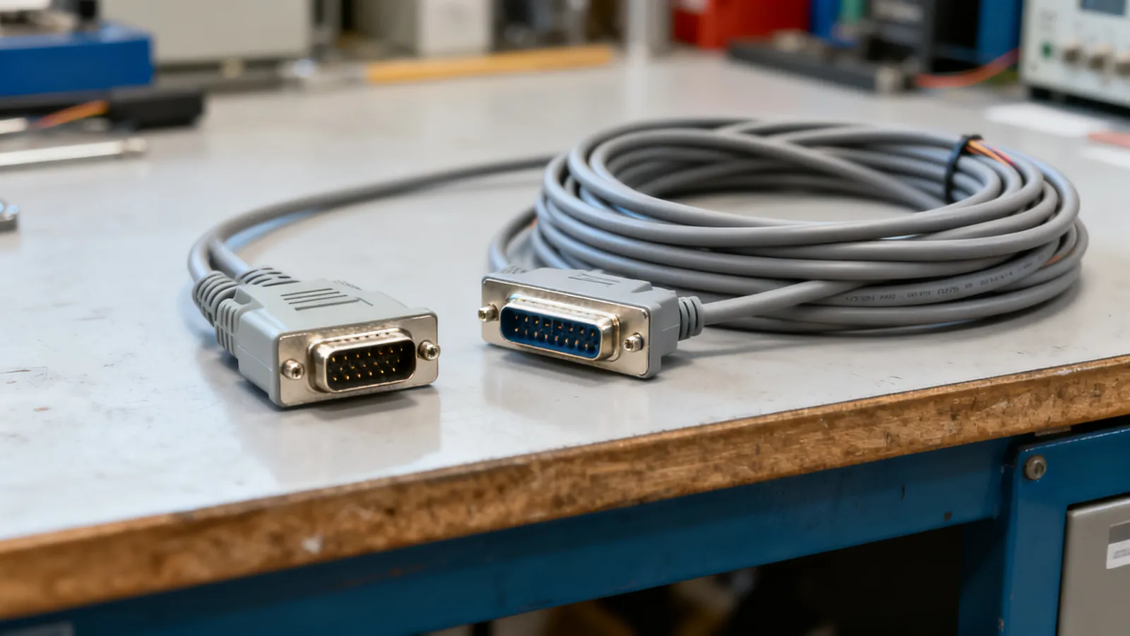
RS-232 Pinouts: DB9 and DB25 Explained
Complete RS-232 pinout reference for DB9 and DB25 connectors: DTE and DCE pin assignments, voltage levels, cable limits, and the TTL mistake that damages boards.
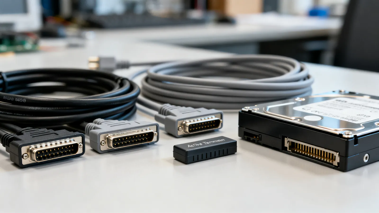
SCSI Cables, Connectors and Terminators
SCSI cable types explained: 50-pin, HD68 and SCA-80 connectors, narrow vs wide buses, SE, LVD and HVD signalling, termination rules and length limits.
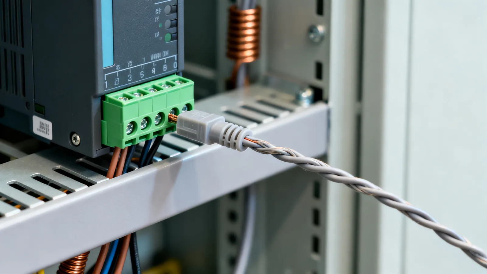
RS-422 vs RS-485: Differential Serial Compared
RS-422 is one driver to many receivers; RS-485 is a true multipoint bus. Compare distance, speed, termination and wiring, and see what damages hardware.